For the XLR8 competition 2015, we had made a remote control on android for the teams to operate their bots. The remote control used the android phone’s bluetooth to connect to an HC-05, followed by an ATtiny 2313 chip to decode the incoming bits. The XLR8 bots usually run on differential drive mechanism, so they require four inputs namely:
- Left Front
- Left Back
- Right Front
- Right Back
More on differential drive here: wiki/Differential_wheeled_robot
Each can be represented by one bit. So we had four output pins of the ATtiny going to four inputs of the Motor Driver (L293D in our case). After that it just boils down send the correct bit sequence from the phone based on the button pressed (i.e. control expected).
ATtiny Board
Designed by Ajinkya Gorad
Schematic:
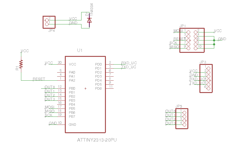
- JP1 is where the programmer head attaches
- JP3 is where HC-05 is attached
- JP5 is the 4 bit output which is sent to motor driver
Connections are pretty straight forward. The RX/TX from HC-05 are joined with TX/RX of ATtiny (PD0 and PD1), and PB0-PB3 are designated the output pins. You should check the programming header connections in the datasheet. One thing we observed while testing was that due to loose connections in the voltage supply, the ATtiny would restart even if the connection went loose for a moment. This happened quite frequently while the bot was running, and this would stop the bot (the init conditions were to set all output pins to 0). For this we soldered a 47uF capacitor externally on the voltage supply pins (polarity matching).
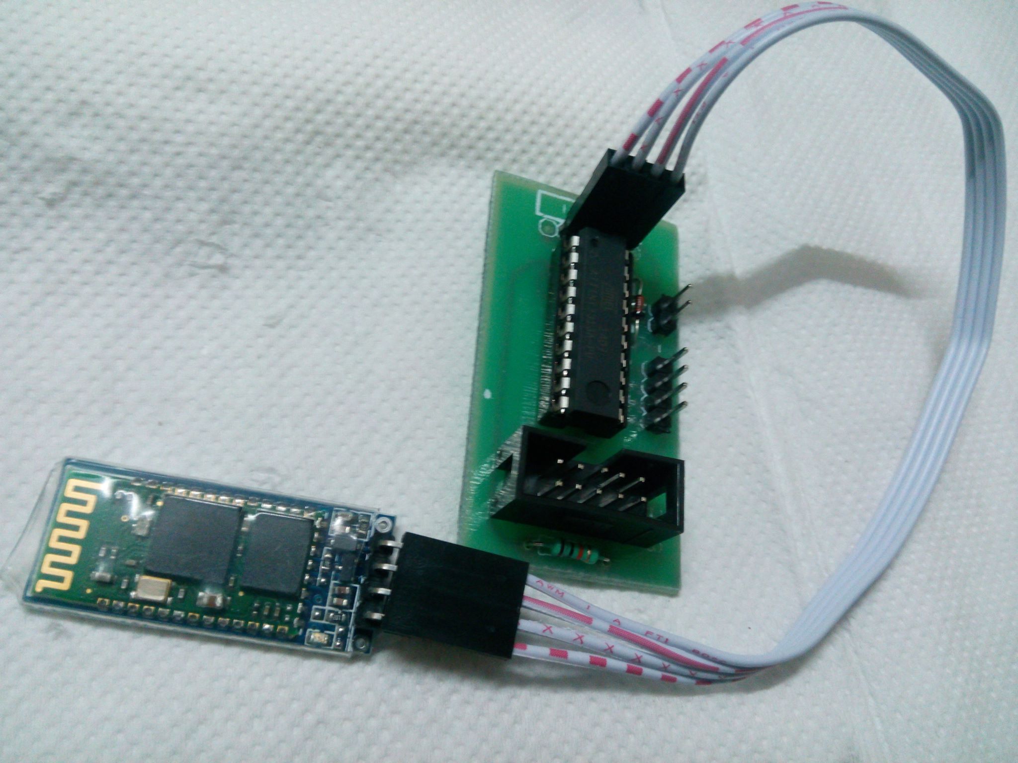
We designed a PCB with respect to this schematic. You can find the necessary Gerber files on the github repo here. This is how it finally looks like:
AVR Code:
Code is pretty straight forward too. Take the bit-sequence from HC-05 through UART and output it on the four pins of PORTB. I have posted the relevant main() function here. Entire code can be found on github.
int main() {

    USARTInit(5, 0, 1); // initialise uart to baud rate 9600, no parity , 1 stopbit
    DDRB=0xFF;			// make all pins on port B as output
    PORTB  = 0x00;		// initially make all pins low

    while(1){		//endless loop
        while( !(UCSRA & (1<<RXC))) ;	// wait for data to be received in uart UDR register
        char temp = UDR;
        PORTB = temp;		//directly write value of uart data to port
    }
}
Android App:
The ATtiny is programmed to output the bit sequence as is. So once you send a bit sequence corresponding to “move forward”, the bot wont stop until you send another bit sequence corresponding to “stop”. The UI consist of three control modes:
- Motion Control: Front, Back, Left, Right control
- Individual Motor control: Left Front, Left Back, Right Front, Right Back
- Swag Mode :D: Hand-tilt based control. Tilt phone forward to move forward, and so on
Motion and Individual Motor control have buttons which on pressed send the bit sequence corresponding to the motion, and on released send bit sequence “stop”. In tilt control mode it check tilt on each axis x and y, if it is beyond a threshold (positive or negative) it sends that motions bit sequence else it sends “stop”.
We also need to consider cases when two buttons are pressed together (which is necessary in Individual Control mode). So we controlled each bit individually on pressed and released rather than sending the whole bit sequence entirely. And we also made a function which would send the latest updated bit sequence which could be called after every update. The entire code is available on github.
Here is the onTouch button code. You can see how the on pressed and on released events ( represented by ACTION_DOWN and ACTION_UP respectively). Rest of the functions used are quite obviously named. For the entire file, check the github repo.
@Override
public boolean onTouch(View v, MotionEvent event){
    boolean updated = true;
    switch(event.getAction()) {
        case MotionEvent.ACTION_DOWN:
            Log.d(TAG, "Action Down");
            v.setPressed(true);

            // Switch case to set a corresponding
            // bit sequence according to the button pressed
            switch (v.getId()) {
                case R.id.forward:
                    setBit(LT_MOTOR_FWD,1);
                    setBit(LT_MOTOR_BCK,0);
                    setBit(RT_MOTOR_FWD,1);
                    setBit(RT_MOTOR_BCK,0);
                    break;
                case R.id.backward:
                    setBit(LT_MOTOR_FWD,0);
                    setBit(LT_MOTOR_BCK,1);
                    setBit(RT_MOTOR_FWD,0);
                    setBit(RT_MOTOR_BCK,1);
                    break;
                case R.id.left:
                    setBit(LT_MOTOR_FWD,1);
                    setBit(LT_MOTOR_BCK,0);
                    setBit(RT_MOTOR_FWD,0);
                    setBit(RT_MOTOR_BCK,1);
                    break;
                case R.id.right:
                    setBit(LT_MOTOR_FWD,0);
                    setBit(LT_MOTOR_BCK,1);
                    setBit(RT_MOTOR_FWD,1);
                    setBit(RT_MOTOR_BCK,0);
                    break;
                case R.id.left_fwd:
                    setBit(LT_MOTOR_FWD,1);
                    break;
                case R.id.left_bck:
                    setBit(LT_MOTOR_BCK,1);
                    break;
                case R.id.right_fwd:
                    setBit(RT_MOTOR_FWD,1);
                    break;
                case R.id.right_bck:
                    setBit(RT_MOTOR_BCK,1);
                    break;
            }
            break;
        case MotionEvent.ACTION_UP:
        case MotionEvent.ACTION_CANCEL:
        case MotionEvent.ACTION_OUTSIDE:
            Log.d(TAG, "Action Up");
            v.setPressed(false);

            // Similar switch case to reset bits when button is left
            // In effect the motion of bot will last till the button is pressed
            switch (v.getId()) {
                case R.id.forward:
                case R.id.backward:
                case R.id.left:
                case R.id.right:
                    reset();
                    break;
                case R.id.left_fwd:
                    setBit(LT_MOTOR_FWD,0);
                    break;
                case R.id.left_bck:
                    setBit(LT_MOTOR_BCK,0);
                    break;
                case R.id.right_fwd:
                    setBit(RT_MOTOR_FWD,0);
                    break;
                case R.id.right_bck:
                    setBit(RT_MOTOR_BCK,0);
                    break;
            }
            break;
        default:
            updated=false;
            break;
    }

    // Check if updated, and then only send
    // We don want to unnecessarily send data
    if(updated) sendMessage(mMotorState);
    return true;
}
R.id.<forward|backward|left|right> correspond to the Motion Control buttons. R.id.<left_fwd|left_bck|right_fwd|right_bck> correspond to the Individual Motor control.
The code responsible for Swag mode:
@Override
public void onSensorChanged(SensorEvent event) {

    float x = event.values[SensorManager.DATA_X],
          y = event.values[SensorManager.DATA_Y],
          z = event.values[SensorManager.DATA_Z];

    ((TextView)mContext.findViewById(R.id.swag_x)).setText("x: "+x);
    ((TextView)mContext.findViewById(R.id.swag_y)).setText("y: "+y);
    ((TextView)mContext.findViewById(R.id.swag_z)).setText("z: "+z);

    int old = mMotorState;

    if(x>6){
        setBit(LT_MOTOR_FWD,1);
        setBit(LT_MOTOR_BCK,0);
        setBit(RT_MOTOR_FWD,0);
        setBit(RT_MOTOR_BCK,1);
    } else if(x<-6){
        setBit(LT_MOTOR_FWD,0);
        setBit(LT_MOTOR_BCK,1);
        setBit(RT_MOTOR_FWD,1);
        setBit(RT_MOTOR_BCK,0);
    } else {
        if(x>4){
            setBit(LT_MOTOR_FWD,1);
            setBit(LT_MOTOR_BCK,0);
            setBit(RT_MOTOR_FWD,0);
            setBit(RT_MOTOR_BCK,0);
        } else if(x<-4){
            setBit(LT_MOTOR_FWD,0);
            setBit(LT_MOTOR_BCK,0);
            setBit(RT_MOTOR_FWD,1);
            setBit(RT_MOTOR_BCK,0);
        } else {
            if(y>4){
                setBit(LT_MOTOR_FWD,1);
                setBit(LT_MOTOR_BCK,0);
                setBit(RT_MOTOR_FWD,1);
                setBit(RT_MOTOR_BCK,0);
            } else if(y<-4){
                setBit(LT_MOTOR_FWD,0);
                setBit(LT_MOTOR_BCK,1);
                setBit(RT_MOTOR_FWD,0);
                setBit(RT_MOTOR_BCK,1);
            } else {
                reset();
            }
        }
    }

    ((TextView)mContext.findViewById(R.id.swag_bits)).setText("bits: "+Integer.toBinaryString(mMotorState));
    if(old!=mMotorState)
        if(mChatService.getState() == BluetoothChatService.STATE_CONNECTED)
            sendMessage(mMotorState);
}
This code has a little complicated logic. So the first two ifs check if there is a hard-tilt (high angle), then we send hard-left/hard-right control bit sequence. If not we check for soft-tilt and send those corresponding bit sequences if true. These tilts are in the x-axis i.e. the left-right axis. Now we go on to the front-back axis i.e. y-axis which is the last nested if in the else condition.
The bluetooth relevant code was taken from the BluetoothChat sample app provided by android. These two functions above are part of the BotControl class which is used in the UI as an onTouchListener and SensorEventListener to capture both touches and tilt changes.