What is the best time for lukha? After the mid-sem or end-sem examinations. I and my friends, Dhrumil and Manas wanted to have some fun with the arduino, so we decided to make some game using it. After a long discussion, we chose to make the classic arcade game ‘ PONG ‘.
The first thing we had to do was build a screen to play the game. So, we chose to make a 7*5 LED array(matrix) for our screen.
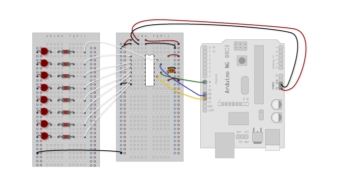
The Circuit Diagram for the Screen :
To check whether the LED matrix was working properly, we tried to make a scrolling LED display(Like the one in a Railway Station).
It was after we did this that we realized a major flaw in the circuit design of the above LED matrix.
Suppose we want to on the LED ROW 3 and COL 3, and LED ROW 4 COL 4, we will ground COL 3 and COL 4 and give HIGH to ROW 3 and ROW 4. But in this process, the LED’s in ROW 3 COL 4 and COL 3 ROW 4 will also light up as they have received the power supply as well.
In fact, if we try to light up all the diagonal LED’s in a square matrix, the whole matrix will light up because we are effectively powering up the whole matrix.
So, because of this glitch, we were forced to temporarily give up on this idea.
Another thing we could have done was power up each LED individually, that is control each LED individually. But, this would need 35 pins on the arduino, and the arduino does not have that many pins. So, we had to either use an Arduino Mega board with more pins, or we would have to come up with some other idea. So while coming up with alternatives, we came across an IC called a ‘Shift Register’. What it basically does is allow us to control as many LED’s as we want using only 3 pins of the arduino board. So, we modified our circuit and connected each LED individually using the shift registers. This way, we were able to control each LED individually.
Overall, it was an excellent learning experience for all of us, as we learnt a lot, mainly how to debug such circuits, and, we also learned how to use shift registers in circuits.
How Shift Registers Work
Learning such an amazing and useful device such as a shift register has been a wonderful experience in itself. Controlling how many ever outputs you want using only 3 pins of the arduino is something very useful for folks who are short of pins(like us).
A Shift Register is basically a cascade of flip-flops in which the output of one flip-flop is connected to the input of the next one.
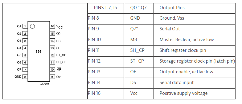
Pin Layout and Function Table : (IC is 74HC595)
Circuit Diagram :
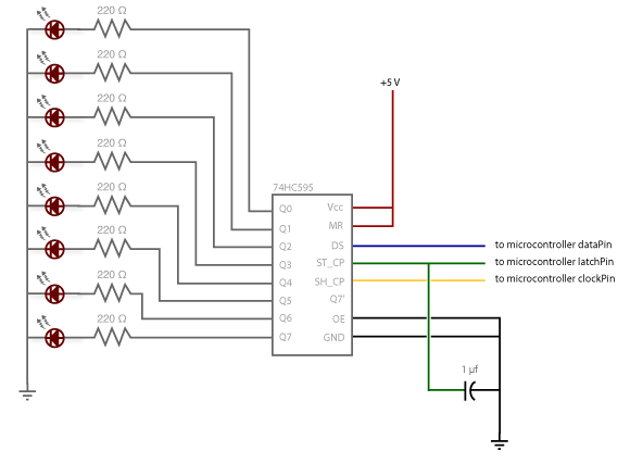
Arduino Connection Diagram :
This is how the IC works :
-
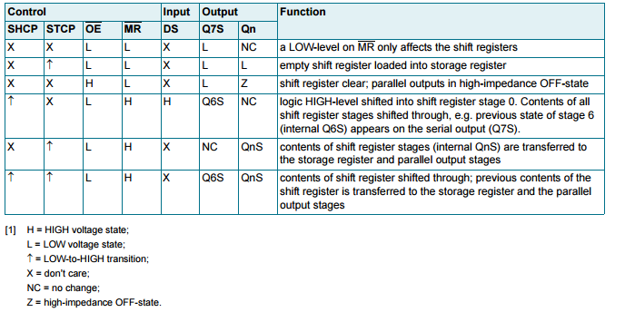
We have three main pins, STCP(Latch), DS(Data), SHCP(Clock). We transfer the data to the first pin of the shift register. The value of the bit transferred is the same as the input given to the data(DS) pin , if the DS pin is high, a high(1) bit is transferred to the first pin, whereas if the DS pin is LOW, a low(0) bit is transferred.
-
Now, the next thing we have to do is shift this bit to the next register. This is achieved by pulsing the clock(SHCP) pin ( Giving it a low to high voltage transition ). Thus, the bit which is stored in one register is shifted to the next one.
-
Then, we continue pulsing the Clock Pin, until we have set the required output on all the shift registers.
-
After all the data has been stored in the registers, it is time to put them on their respective output pins. This is achieved by pulsing the latch(STCP) pin( Giving it a low to high voltage transition ).
Using one Shift Register, 8 outputs can be controlled. If we want more outputs, we have to attach more than one shift registers by connecting the Serial Out pin of one shift register to the DATA pin of the next register. Thus, using 5 shift registers, we were able to control 35 LED’s for our game.
References:
You can refer to the following video to get a clearer understanding of the working principle of shift registers.
https://www.youtube.com/watch?v=6fVbJbNPrEU