Electronics club conducted its last electrified session on 18th March, 2017. It was totally awesome as we got an opportunity to make a half adder, full adder, subtractor and priority encoder. Along with that we also learnt some cool stuff about digital circuits.
##Where do we begin from to make anything as simple as an adder?
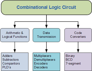
We basically use a combinational circuit. Not only an adder but we can even make a subtractor, priority encoder, MUX and what not!
Combinational circuit is basically used for making those circuits which depends on the current state.
##So, let us now begin with how exactly do these combinational circuits function:
Adder:
As you can guess an adder simply add two numbers. But why do we need a complicated circuit to just add numbers? Actually, adders are used in the arithmetic logic units in many computers and other kinds of processors.
There are two kinds of adders:
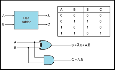
1) Half adder
2) Full adder
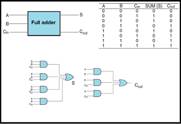
The major difference between a half adder and a full adder is that a full-adder has three inputs and two outputs where as a half adder has only two inputs and two outputs. In a full adder, the first two inputs are A and B and the third input is an input carry.
The circuit diagram and truth table of a half adder and full adder is shown below:
Subtractor:
Similarly, a subtractor subtracts two numbers. They are also of two types and as you can guess the two types are:
1) Half subtractor
2) Full subtractor
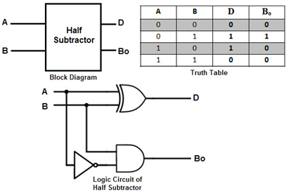
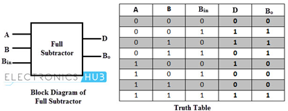
Just like in an adder, the subtractor has similar inputs just the difference is that instead of a carry we have a “borrow”.
The circuit diagram and truth table of a half subtractor and full subtractor is shown below:
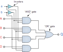
Priority Encoder:
So basically, what a priority encoder do is that it gives the highest priority of the current input as an output. So, when an input with a higher priority is present, all other inputs with a lower priority will be ignored. The priority encoder comes in many different forms with an example of an 8-input priority encoder along with its truth table shown below.
8-to-3 Bit Priority Encoder:
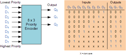
Where X equals “don’t care”, that is it can be either logic “0” or logic “1”.
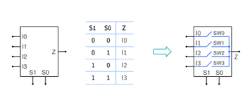
Multiplexer (MUX) and Demultiplexer:
How are multiple signals combined?
MUX is used for this purpose. It has N Select lines, 2N input lines, and it routes one of the input lines to the output. Conceptually, a MUX may be thought of as 2N switches. For a given combination of the select inputs, only one of the switches closes (makes contact), and the others are open.
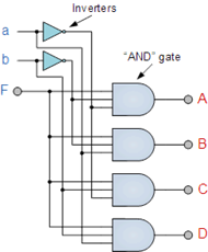
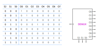
It is obvious from the name that a demultiplexer do the reverse of what a multiplexer do. It takes a single input (I) and routes it to one of the output lines. For N Select inputs, the number of output lines is 2^N.
Circuit diagram and truth table of a multiplexer is shown below:
Circuit diagram and truth table of a demultiplexer is shown below:
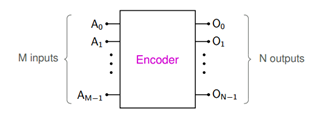
Encoders and Decoders:
You might be wondering what is the need of an encoder?
It is actually used to convert information from one format to another for the purpose of standardization, speed and compressions.
In encoders, only one input line is assumed to be active. The binary number corresponding to the active input line appears at the output pins. The N output lines can represent 2N binary numbers, each corresponding to one of the M input lines, i.e., we can have M = 2N. Some encoders have M < 2 N.
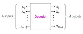
Similarly, you can guess the functioning of a decoder. For each input combination, only one output line is active (which means 0 or 1, depending on whether the outputs are active low or active high). Since there are 2N input combinations, there could be 2N output lines, i.e., M = 2N. However, there are decoders with M < 2 N as well.