Arduino is a great open-source electronics prototyping platform based on flexible easy-to-use hardware and software. It is basically a simplified microcontroller, in the sense that it uses a normal microcontroller and envelopes its internal functioning which may impede its functioning, but it gives us a very handy, easy to use tool. It is also much simplified as compared to other microcontrollers, because the preset standards/code in any Arduino eliminates the need to know the internal details of the microcontroller before using/programming it.
In order to get the best out of this tutorial, please read through the links which you are asked to refer in the following text(Other links are for detailed information only). This will furnish you with the information required to understand the examples mentioned.
Why Arduino
- Uses ATMEL AVR Microcontrollers, which give excellent performance at cheap cost.
- Has built-in ADC,PWM Pins.
- Open Source!
- For us, it is the most easy microcontroller to start with, which you will see in some time :)
Contents:
Installation
Arduino comprises of 2 main parts:
-
An Integrated Development Environment(IDE) for writing the Code you want the microcontroller to execute
-
Arduino Boards that comprise of the enveloped microcontroller and other peripheral elements(like bootloader code,ICSP) to ensure proper functioning when used from a PC.
These 2 parts now primarily explain our method of using Arduino. We will write the code(also called ‘Sketch’) on the IDE, setup the hardware connections and upload the code onto the board to implement it.
Arduino uses its own IDE for programming. The coding is similar to C, except the deviations due to hardware of the board.
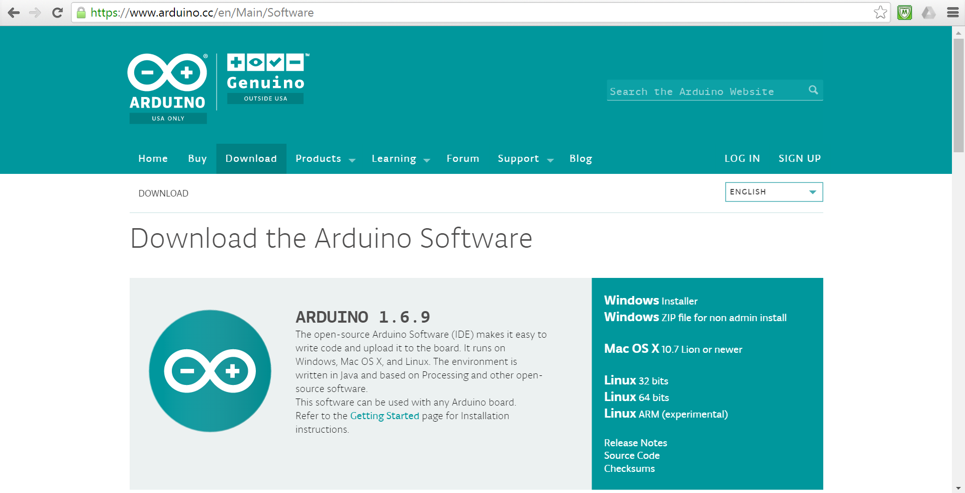
Download the Arduino IDE from: https://www.arduino.cc/en/Main/Software.
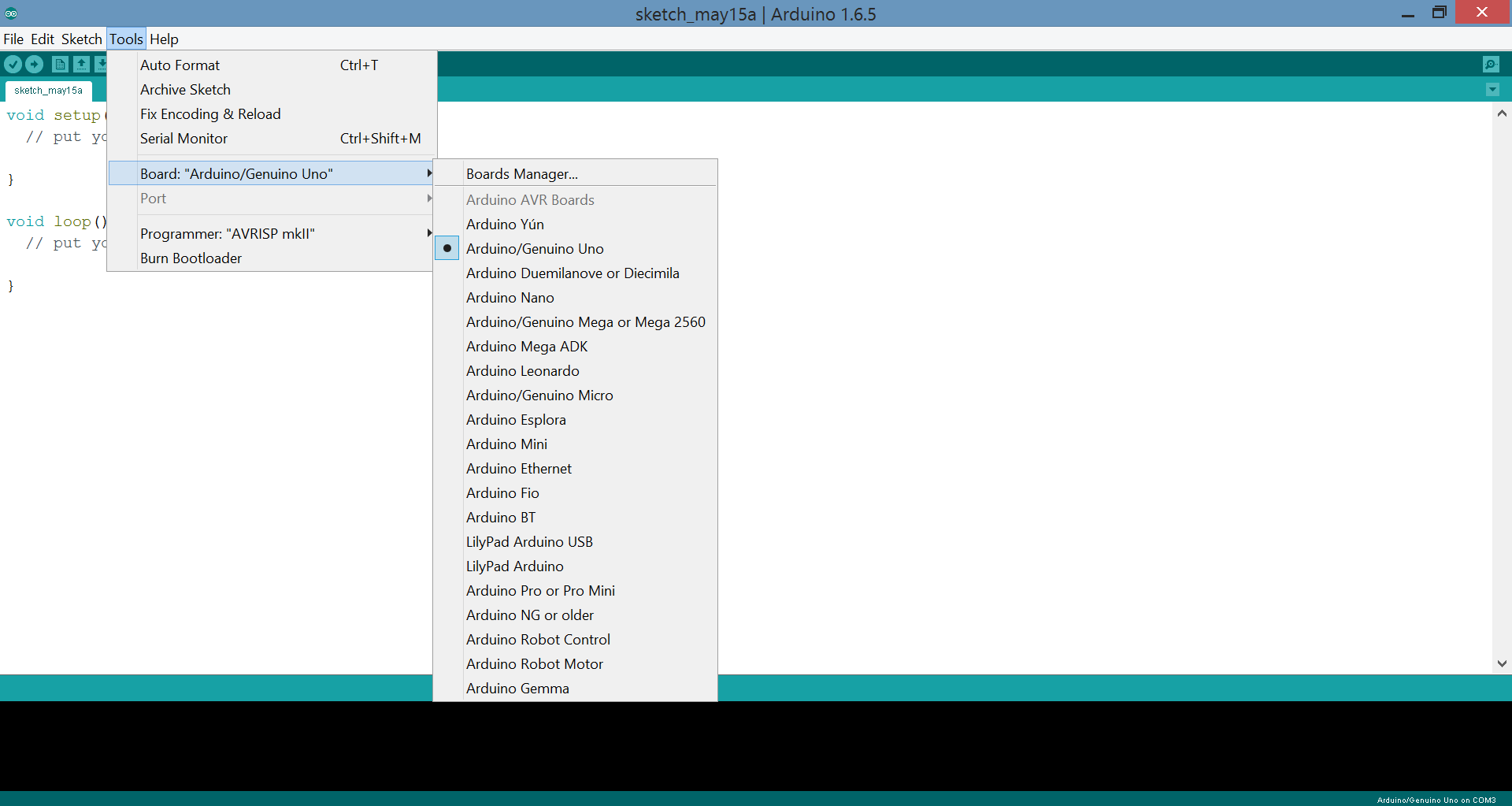
Note: After installing the IDE from the Arduino website shown above, you must select the board that you are using in Tools>Board:Name.
The USB Port must also be selected appropriately but that will be taken automatically in most cases. After this, on connecting, and “Uploading”(Sketch>Upload) any sample code onto the board you should get a message verifying the amount of space available on the board etc, and then a message showing successful upload process.
Done, now the board is verified and ready to use with any custom code.
First Look
Arduino offers different boards, with varying microcontroller capability(memory and clock speed) and number of input/output pins.
Let us examine one of the simple models, Genuino.
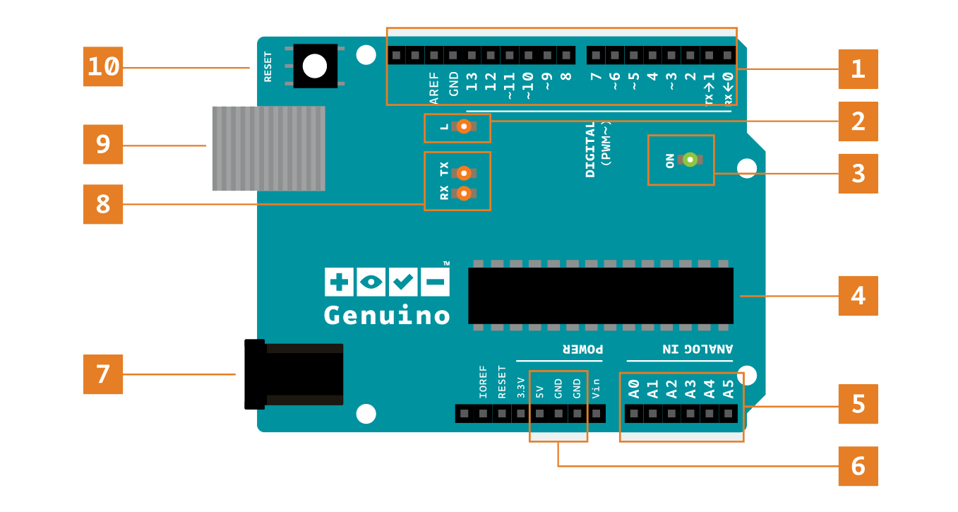
The parts, as labelled in the figure, are explained here:
Digital pins
Let us get a decent idea about the variety of pins available on any Arduino. There are pins which can be used in different modes. As you can see, pins numbered 2-13 are Digital Input/Output pins(0,1 are serial in/out). That is, they are capable of giving/taking Digital output/input. But, the ones which are PWM Enabled (shown by a ~) can also be used as Analog Outputs.
Here, Input/Output is the “Mode” (specified by pinMode()) in which the pin is used. Use these pins with digitalRead(), digitalWrite(), and analogWrite() commands according to the mode. analogWrite() works only on the pins with the PWM symbol.
Note that of the Mode is not explicitly specified using pinMode(), they are set to Input.
Also, most of the Analog Pins(mentioned at point 5), can be used as Digital Pins.
Please refer: https://www.arduino.cc/en/Tutorial/DigitalPins for details.
On-board LEDs and Switches
Pin 13 LED: The only actuator built-in to the board. Useful for debugging, since the LED is in-built and hence reliable in terms of connections.
Power LED: Indicates that the board is receiving power. Useful for debugging.
Reset button: Resets the ATmega microcontroller.
Analog in
These pins, numbered A0 to A5 can be used for Analog inputs/outputs(ADC etc) with analogRead(), analogWrite() and also digitalWrite() as General Purpose Input/Output pins.
Please refer: https://www.arduino.cc/en/Tutorial/AnalogInputPins for details.
Gnd and Vin pins
Vin is the input voltage to the board when it’s using an external power source (as opposed to 5 volts from the USB connection or other regulated power source from the power jack). You can supply voltage through this pin(from external circuitry), or, if supplying voltage via the power jack, access it through this pin.
Power connector
This is how you power the board when it’s not plugged into a USB port for power. Can accept voltages between 7-12V(But the voltage is regulated to a maximum of 5V)
(You can read the “Power” section of https://www.arduino.cc/en/main/arduinoBoardUno for in-depth understanding of power pins, and the voltage regulator.)
TX and RX LEDs
These LEDs indicate communication(send/receive) between the board and the computer. Expect them to flicker rapidly during sketch upload as well as during serial communication. Useful for debugging.
USB port
Used for powering the board, and most importantly, uploading your sketches to the board. It is also used for communicating with the sketch (via Serial. println() etc.).
An understanding of how we will use these pins, and what functions can they perform for us will be gained through the examples that follow later.
Details: If you are interested, you may refer the Technical Specs, Power, Input/Output(Special Pins) and Communication sections of this page: https://www.arduino.cc/en/Main/ArduinoBoardUno.
I would advise you to look into the details given here atleast once. Read them after you get familiar with these things, if not right now.
Programming the Arduino
Please Refer: https://www.arduino.cc/en/Tutorial/Sketch for basic functions and guidlines on Sketching.
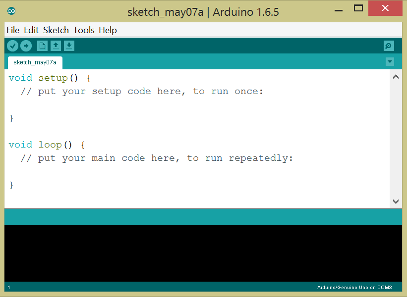
The program is written in the IDE, Verified(compiled) and Uploaded(burnt) to the board.(Writing the program into the memory on the board so that it executes this program after disconnecting from PC)
We shall see the use of the programming language through the examples that follow later.
Common Usage Examples:
Make Sure you understand the function behind each line of the code given below
int pin=13
/* variable declaration, refers to pin Numbered 13 */setup()
/* code in this definition runs only once and acts as a setup as the name suggests */loop()
/* code here runs repeatedly */pinMode(pin,INPUT)
/* sets pin numbered “pin” to an INPUT pin */digitalWrite(pin, HIGH)
/* gives High(Vin) voltage output at pin(provided it is set as Output) */digitalRead(pin)
/* analogous to digitalWrite, but for INPUT pins */analogWrite(pin,Value)
/* a number between 0 and 255(0 to 100% duty cycle)(use on PWM enabled pins \~) */analogRead(pin)
/* returns Digital Converted input as number between 0 and 1023 */delay(t)
/* very useful in introducing delay, of t milliseconds */For details you can look up the concerned command on the Arduino website. It has a “References” section that has just these things!
The Iconic LED Blink
The Connections(Mentioned in Setup)
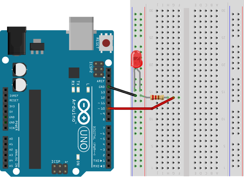
This being our first time, let us look into the setup closely. Please read the comments of the code that follows to understand it thoroughly.
- The code will be written in the IDE and burnt onto the board.
- The board must be connected to an LED at pin numbered 10(digital).
- It is clear that the board gets its power from the PC USB itself.
- After the code is successfully uploaded(this will be shown on the PC screen, and can be inferred from the stoppage in flickering of the TX/RX LEDs, showing that the transfer is over) the LED must be turning on/off after 1 second every time.
We can remove the USB if there is external power connection, because the code is stored in the memory
Code
int myLED=10; //variable declaration


// the setup function runs once when you press reset or power the board

void setup() {
    // initialize the pin connected to LED as an output.

    pinMode(myLED, OUTPUT);
    //pinMode(Number,Role), gives the pin with that number, the specified

    //role i.e. either it will act as an output pin or an input pin!

}

// the loop function runs over and over again forever

void loop() {
    digitalWrite(myLED, HIGH);
    //“writes” the pin at number “myLED” with HIGH state voltage(mostly 5V)

    //corresponding command for input pin is digitalRead

    delay(1000); // wait for a second

    digitalWrite(myLED, LOW); // turn the LED off by making the voltage LOW

    delay(1000); // wait for a second

}
Hardware
The LED is connected to Pin no.10, which is a Digital Pin, hence can have a high or a low voltage output/input. That’s all.
This is basically, giving the desired output at the desired pin. Using this, you can do the same for analog pins(using analogWrite/analogRead), and this will be used in everything you will make further.
Note: It is a good practice to mention the hardware connections as comments in the Sketch. Due to this, the implementation of actual circuit connections becomes easy.
Functionalities in Arduino
Pulse Width Modulation
Pulse Width Modulation is the technique of producing Analog-type results by Digital means, and essentially relies on very fast toggling of the digital output between high and low at appropriate time intervals.
Refer to the theory of PWM here: https://www.arduino.cc/en/Tutorial/PWM
I strongly advise you to see the above link to get a feel of what PWM is before proceeding.
The PWM Enabled pins on Arduino(3,5,6,9,10,11) can be used as analog outputs with a resolution of 0-255. This can be interfaced with ADC.
Using this functionality, Arduino essentially eliminates the involvement of duty cycle calculation and digital pin manipulation, because of the inbuilt functions analogWrite. This is the power of Arduino! Functions are already inbuilt for you. In other microcontrollers, you need to literally write such functions.
Note: The PWM Enabled pins do NOT give Analog output, but they give the Pulse Width Modulated Rectangular waves as outputs.(Read Link)
Code
int ledPin = 9; // LED connected to digital pin 9

void setup() {
// nothing happens in setup

}

void loop() {
    // fade in from min to max in increments of 5 points:

    for (int fadeValue = 0 ; fadeValue <= 255; fadeValue += 5) {
    // sets the value (range from 0 to 255):

    analogWrite(ledPin, fadeValue);

    // wait for 30 milliseconds to see the dimming effect

    delay(30);

    }
}
Note: Delays are very important while coding microcontrollers. Their typical computing speeds lie in ranges of 1MHz, and hence execution of any average statement in the code would take approximately 1μs.
If the above code would be executed without the delay(30) statement, out human eye wouldn’t be able to perceive the changes so fast and would see a constant average brightness.
Also, in many Analog operations, it is advisable to wait for a short period of time in order to avoid noise in the system.
Hardware: An LED is connected between pin numbered 9 and ground.
Analogue-Digital Conversion
Arduino highly simplifies Analog-to-Digital Conversion. It is used as follows:
Suppose we have Analog Input at a certain pin, say A0.
Executing analogRead(A0), would return a number from 0-1023 (default, 10-bit resolution), representing the Digital Equivalent of the given Analog Input, with 5V as reference(1023).
Can you guess where this function is required?
Well, as an example, it is required to capture sensor values which can have any value between 0 to 5V and we want the exact value. Try thinking of more such examples.
Once again Arduino simplifies matters for you, because the actual theoretical procedure of ADC is different altogether. Instead, that comes as an inbuilt function and it directly returns the corresponding value with the given resolution and reference voltage.
Note: Though not often required but we can change the reference value, by supplying the reference voltage at the AREF pin, and using the analogReference() command.
In AVR microcontrollers, executing ADC requires something called interrupts. As you might have seen, all this is not explicitly required in Arduino. Again displaying the ease of using Arduino.
Note: Uno is also provided with special interrupt pins, mentioned in the link given in “Details” section.(Do not worry about “interrupts” right now, if you don’t know what is is)
Interfacing with Peripherals
We often come across an interface between Arduino and various other useful elements. We will understand how to interface an Arduino with LCDs and the Computer(or in general any other unit, by Serial Communication), using Standard Libraries, interfacing with different sensors etc.
LCD Display
In order to teach the Arduino how to communicate with an LCD screen(send the data we want for display) we use a library: “LiquidCrystal”. It is provided by default in most cases. This library contains functions to interface Arduino with an LCD, like declaring an LCD Screen of given size, print given characters etc.
Please refer all the functions given on the right hand side of this page: https://www.arduino.cc/en/Reference/LiquidCrystal.
After understanding the functions, you can move on to examples (File>Examples) and read them from the link given above or in your IDE itself.
The important part in interfacing with LCDs is the hardware connection:

The marked rectangle contains the names of the 16 pins that are usually available on an LCD. From them, we connect 8 pins whose numbers are marked in bold in the next column. They are connected to corresponding pins in the Arduino as shown.
Data 4-5-6-7 are data pins which will carry information on What to print. 5V and GND powers the LCD. Enable and R/S pins are also required for enabling and operation selection.
Note: You can also connect Contrast pin, to a potentiometer output between 5V and GND, so as to achieve variation in contrast.
Serial Communication
This is a way of microcontrollers to communicate to other microcontrollers or computers. In Arduino, serial communication with the computer can be achieved easily through the USB channel used for programming it.
The library used for this purpose is “SoftwareSerial”, and is there by default.
Look up the functions of this library here: https://www.arduino.cc/en/Reference/SoftwareSerial.
Its examples will also be useful in understanding serial communication.
Note: We do not use the pins 0 and 1 for serial communication with computer because that occurs through the USB cable itself.
Ultrasonic Sensors
This sensor measures the time duration between sending an ultrasonic sound pulse and receiving back its reflection from the object in front of it. From this time difference, it estimates the distance to the object in front!
In order to use this without processing the data in the form in which it comes from the sensor, we use a library developed for the purpose, named “NewPing”.
Note: We can use it without the library(but with certain information to convert the time duration of received HIGH pulse to distance, using default library “ping”), by generating our own pulse and then reading the reply on our own. But that is tedious.
Refer: http://playground.arduino.cc/Code/NewPing for the constructors,methods of this library.
Adding external libraries, Accessing examples
Download the library from http://playground.arduino.cc/Code/NewPing. Unzip it. Place the folder NewPing in this location: Arduino>Libraries. Restart the Arduino IDE. You will now find this library under Contributed Libraries section in: Sketch>Include Library.
You can access examples of this library(and all others) from File>Examples>NewPing.
What Next?
Keep Tinkering!
Keep thinking of applications of the mentioned features.
- As a basic example, this could enable you to take readings of some physical quantity from sensors that return analog values, execute ADC(inbuilt) and give Pulse Width Modulated output to motors. So, you can use Arduino as the motor driver, and make the Line Follower Bot!
- Arduino can be used in many small projects when coupled with a General Purpose Input/Output board, typically having LEDs, Switches, Potentiometer, Buzzer, LDR, TSOP IR Receiver, Temperature Sensor(LM35D) etc elements.
The Open-Source Advantage
You can follow the official Arduino Blog for ideas, or explore the Arduino website for in-depth understanding of Arduino!
Thank you.