New to the world of electronics? Or are you a regular tinkerer who is having troubles in some basic concepts? Well you have come to the right place then. A bunch of electronics enthusiasts have compiled a wonderful list of topics that you might need in your projects.
Contents:
Operational Amplifiers
Operational Amplifiers
The Operational Amplifier, or OpAmp is an extremely versatile device. It can be used for anything from simple amplification of a signal to solving differential Equations. Here we will discuss mainly OpAmp as an amplifier.
The OpAmp is represented by the symbol-
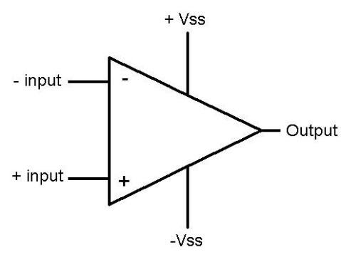
(The +Vss and –Vss pins are often not shown)
The +input is called the non-inverting terminal and the –input is called the inverting terminal. The +Vss pin is generally connected to +15 V and the –Vss to -15 V, with respect to some ground.
The output and the input voltages are related by the expression
Vout= A*(V+-V-)
Where A is of the order of 105. (This varies from OpAmp to OpAmp). Another thing to note about the OpAmp is that it has very high input impedance and very low output impedance- meaning very little current can go into or out of the input pins, and a large current (usually a few hundred milliampere) can flow through the output pin. More about why this is important later.
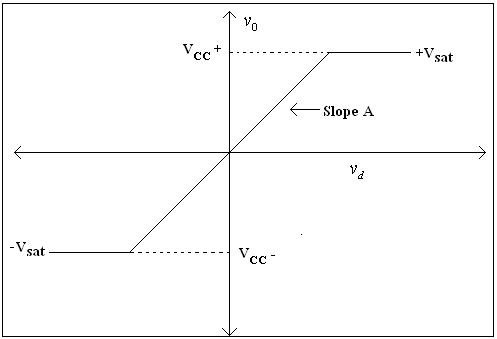
A simple amplifier can be built by grounding the inverting terminal and applying the signal to the Non-inverting terminal. However, this places some severe restrictions. For one, the output voltage, Vout cannot go above +Vss or below –Vss. Hence if the signal voltage exceeds around 150 microvolt, the Output pin saturates to 15 V and the OpAmp no longer works as an amplifier. Moreover, the amplification factor, A is not precisely known and the output voltage cannot be predicted with certainty. This behaviour can be seen in the OpAmp characteristics. (Here, Vd = V+
- V- and Vcc = Vss).
(The region where Vout varies in proportion to Vd is called the linear region and beyond that it is called the saturation region – Vout is said to have saturated to a constant voltage.)
To overcome this difficulty, we come up with another configuration.
The Output voltage is taken between Vout and ground.
Since no current flows into the V- terminal,
V- = Vout * R2/ (R2+RF).
The OpAmp equation becomes- Vout = A (VIN – VoutR2/ (R2+RF)) Vout = AVIN/ (1+AR2/ (R2+RF)) Vout ~ Vin (R2+RF)/R2, (Since A is very large.) Well, that was rather tedious, wasn’t it? Turns out there is an easier way. Let’s take a closer look at the OpAmp Equation.
(V+-V-) = Vout/A
Well, what does this mean? It means that
“The OpAmp will do whatever it can to keep the potential at the input terminals the same”.
And all it can do is change the voltage at the output terminal. This is called a virtual short. The potential at the input terminals is the same, even though they are not connected. This assumption is valid only when the OpAmp is working in the linear region. In the saturation region, the potential at the input terminals need not be the same.
Let’s analyse the above circuit once again. ) Current through Resistor R2 would be Vs/R2, and the same current flows through RF. Hence voltage at Vout is Vs/R2 * (R2+RF). The amplification factor now becomes 1+RF/R2. The input signal can now be anything from a few millivolts to a few volts, and the precise value of A no longer matters. This is one configuration in which the OpAmp can be used as an amplifier.
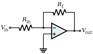
Another such configuration would be,

The output voltage turns out to be Vout = - Vin * RF/Rin. Note that the output is inverted with respect to the input signal. Hence this is the Inverting Amplifier Configuration. The previous configuration was called Non Inverting Mode.
Another use of an OpAmp is to provide a ‘buffer stage’. Normally, large currents cannot be drawn out of sensors, to be used for further processing. However, a reasonably large current can be drawn out of the OpAmp’s output terminal, when used in the following configuration.
(Do note that the current drawn by the external circuit comes through the output terminal of the OpAmp, and negligible current flows into any of the input pins) While in the expression for the amplification factor, only the ratio of resistances appear, care has to be taken to ensure that the resistance values to be used are in the range of 1k to 100k. For a voltage magnification of ten in inverting mode, the most preferred resistances should be 1.5k and 15k.
Another thing to note is that the circuit has to be as ‘clean’ as possible. If the circuit is made in a bread board, care has to be taken to ensure that the wires are as straight as possible, do not form loops, and are only as long as required. The stray inductance that may be formed otherwise may lead to severe distortion of the signal.
When connecting the resistor between the output and input pins( RF in this case) only the inverting terminal has to be used. This resistor is said to provide ‘Negative feedback’. (If the non-inverting terminal is used, the resulting positive feedback would lead to the OpAmp moving to the saturation region easily. However, in some cases, positive feedback is intentionally introduced to create instability. An astable multivibrator, where the output swings between positive and negative values without any user intervention, uses a positive feedback system.)
Some popular OpAmp ICs are the LM741 and the LM 324. The LM324 has four high quality OpAmps integrated into a single chip. You can find the datasheet of the LM324 here. Take a look at the LM741 datasheet here. The datasheet provides additional information on the positions of the pins, supply voltage, maximum output current, blah, blah, blah…..in short, everything you need to get your circuit running.
Multiplexer - Demultiplexer
Multiplexer
Multiplexing is the generic term used to describe the operation of sending one or more analog or digital signals over a common transmission line at different times or speeds and as such, the device we use to do just that is called a Multiplexer. The following is a black-box view of the common digital multiplexer, or MUX (as we fondly call it), which has N selection lines, 2N, input lines, and a single output line.
The 4-to-1 channel multiplexer that is depicted in the adjoining diagram, selects an input line corresponding to the input provided to the selection bits. In this way, a MUX somehow acts like an equivalent of a mechanical multi-way switch.
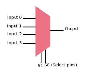
From a coder’s perspective, a multiplexer could be seen as an analogue of the switch-case statement, with the case values represented by the different input values, say I0, I1, I2, and I3, while the value being tested under switch, represented by the binary number S1S0.
Going a little into the logic aspect of it, the multiplexer’s (4:1) truth table looks like the following:
So when does one use a multiplexer? In general, a multiplexer helps transmit multiple data using a single line. For example, a multiplexer is used to increase the efficiency of the communication system by allowing the transmission of data such as audio & video data from different channels via cables and single lines. Another similar application is in linking computer memory to various I/O devices, where multiplexers help reduce number of connecting copper wires.
Demultiplexer
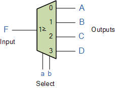
The data distributor, known more commonly as a Demultiplexer or “Demux” for short, is the exact opposite of the Multiplexer. The demultiplexer takes one single input data line and then switches it to any one of a number of individual output lines one at a time. The demultiplexer converts a serial data signal at the input to a parallel data.
The function of the Demultiplexer is to switch one common data input line to any one of the 4 output data lines A to D in our example above. As with the multiplexer the individual solid state switches are selected by the binary input address code on the output select pins “a” and “b” as shown.
Truth table for demultiplexer:
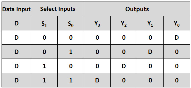
A typical application of the demultiplexer is to control multiple circuit lines using few selection lines. Demultiplexers are used in combination with multiplexers communication system to carry out the process of data transmission. Demultiplexer are also used in serial to parallel conversion. In this technique, serial data is given as an input to the De-multiplexer at a regular interval, and a counter is attached to the demultiplexer at the control input to detect the data signal at the output of the demultiplexer.
The Demonstration
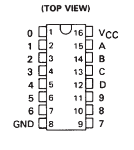
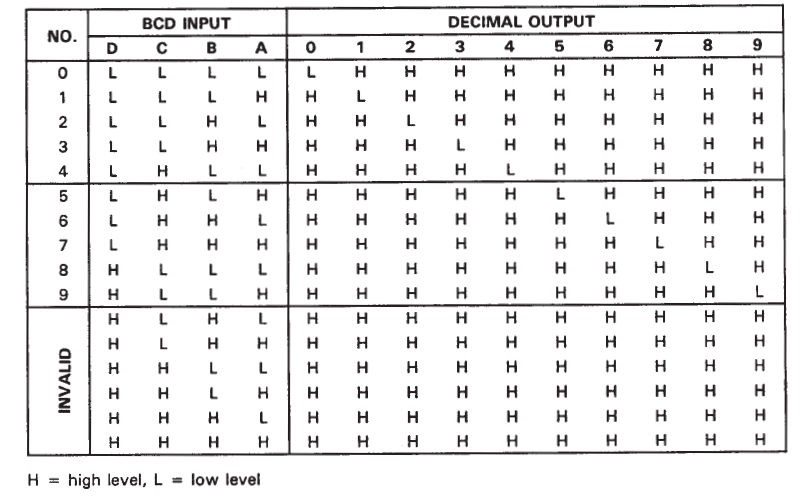
We did a small demonstration to see the working of a De-multiplexer in action. We made use of an IC called SN7442A. (You can find the Datasheet at here.)
Let’s look at the pin configuration of the IC.
Connections of the circuit
Connected Vcc with 5v. Ground to 0v (duh!) As we see in the datasheet (do have a look), D is the most significant input bit and A the least. Since, we wanted to do a quick demo, we keep C and D connected to ground (Low always). So now, we can play with only input pins A and B.
Looking at the output table of the circuit
We see that toggling A,B input pins , we can control pins 0, 1, 2, 3 and hence, we connected 4 LEDs to it. To display the output. A,B were made to toggle from 5v to 0v and vice versa by connecting a button each between inputs and 5v. Also, connecting a resistor between the input and ground does the job. Think about it!
So now, on clicking the 2 buttons separately and together, we see the expected LEDs going Low according to the output table!
Infrared - Passive Infrared Sensors
This summers I took my first project ever in life. Meanwhile I came to stop by a problem in which i had to detect a movement of a object relative to its postion. After lots of googling and stuff , I found the solution to this with the help of sensors , namely IR (infrared) PIR (passive infra red sensors. Lets explore what they are !
IR Sensor
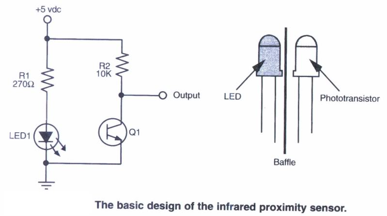
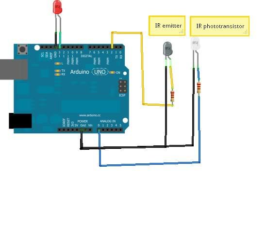
IR sensor consists of a LED and a photodiode. In the same branch as the LED and photodiode there are two resistances with the larger one in the branch with photodiode ( since, it is reverse biased , we demand greater potential drop with small resistance ).The LED is a infrared LED which emits infrared rays and those rays are received by the photodiode when they are reflected by some surface. The circuit is assembled as following :
To check the circuit connect it with arduino:
Now keep your hand at some height above the LED . Meanwhile open the serial monitor on arduino IDE and notice the values on it . Now slowly start bringing your hand towards the LED and notice the increase in value on the serial monitor. These values are a measure of amount of reflection received by the photodiode. The closer your hand is , more is the value on the serial monitor. Thus , this serves as a measure of distance relative to the sensor.
PIR sensor
The next task which i had to conquer was to detect movement . The best way to find this out was a PIR sensor . Ever wonder you go into a room or washroom it lights up by itself ? you know the reason? The answer lies in PIR sensor . Let’s see how this works. The basic function of a PIR sensor is to detect a CHANGE in movement.
It is called passive because unlike the IR sensor it does not have
something which produces energy. In IR sensor IR sensor produces IR rays
which are detected by the photodiode but here there is no such source.
The IR rays which the PIR sensor collects is produced by the movement of
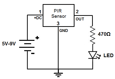
body near it . The circuit of the sensor is as follows :
The PIR sensor contains , inside it , a material called pyroelectric material which produces current on receiving infrared waves. It contains two sensor inside it which give output in opposing ways , thus , any constant position isn’t detected whereas a movement is detected.
Thus if you keep your hand moving in front of it you will constantly receive output but if you will stabilise it the output reading stops. This principle is thus used in washrooms to light up light by itself .
Flex Sensor
A flex sensor is a variable resistor whose resistance changes when it bent. More the sensor is bend, more is the resistance.
The working principle: The black strip is a thin layer of carbon/graphite (for flexibility). The light grey material is patterned and segmented metal electrode. Deformation of the flex apparently increases/decreases the amount of metal in contact with the carbon.
In this tutorial you will learn how to use a flex sensor. In the demo we will control the brightness of a LED using a flex sensor.
Material you will need:
-
A flex sensor
-
Arduino UNO
-
Breadboard
-
10K Ω and 220Ω resistor
-
A LED
The circuit:
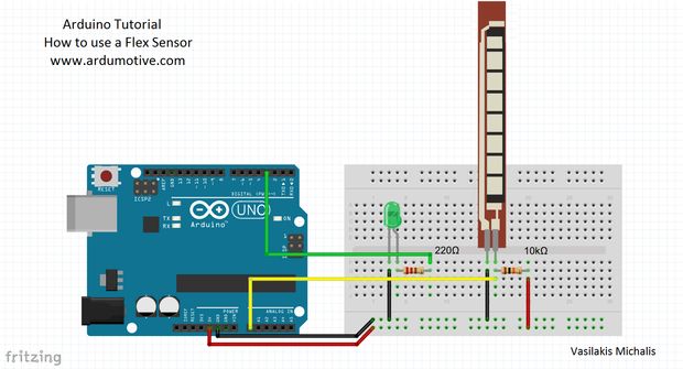
In the circuit, we have attached a fixed resistor of 10kΩ. Thus creating a voltage divider arrangement. Now when the flex sensor is bent, the resistance increases thus increasing the voltage at the junction. This voltage is read by the Arduino and it is mapped to control the brightness of the LED.
Code:
	//Constants:

	const int ledPin = 3; //pin 3 has PWM function

	const int flexPin = A0; //pin A0 to read analog input

	//Variables:

	int value; //save analog value

	void setup(){

		pinMode(ledPin, OUTPUT); //Set pin 3 as 'output'

		Serial.begin(9600); //Begin serial communication

	}

	void loop(){

	value = analogRead(flexPin); //Read and save analog value potentiometer

	Serial.println(value); //Print value

	value = map(value, 700, 900, 0, 255);//Map value 0-1023 to 0-255 (PWM)

	analogWrite(ledPin, value); //Send PWM value to led

	delay(100); //Small delay

	}
We have read the voltage values using the A0 pin on the Arduino.
For controlling the LED we use Pin 3 which is a PWM pin.
For setting the range of the voltage read, you will have to see what the voltage is when the sensor is not bent and when the sensor is bent to its maximum value.
Flex sensors can be used to detect finger movements in a gesture control robotic arm. Reading the voltage values can tell you how much the finger is bent.
Ultrasonic Sensor
It is more often than not that we require our model cars or bots or even basic circuits to measure distance of various objects in their surroundings. For this we require ultrasonic sensors. I am going to discuss the use of a ultrasonic sensor module HC-SR04.
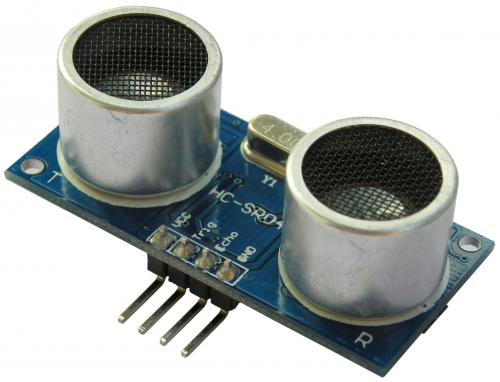
It has a range of 5-400 cm. It contains two transducers- one ultrasonic transmitter and one receiver as well as a control circuit.
HC-SR04 has 4 pins:
-
5V vcc pin
-
Ground pin
-
Trig pin (to input an electronic pulse)
-
Echo pin (to output electronic signal when receiver receives the reflected ultrasonic pulse)
Working
We have to provide a 10uS electronic pulse to Trig pin due to which the transmitter sends a 8 cycle 40kHz ultra sound pulse. Now we calculate the time interval between the sending and receiving of the pulse.
Since, we know the speed of sound in air and we now also know the time taken by the time to go to the object and come back, we can calculated the distance.
So the distance of the object will be at half of our calculated distance.
The Demonstration
I did a small demonstration showing how to use ultrasonic sensor HC-SR04. You can find the datasheet here.
Connections of the circuit
Connections of the circuit are as shown in the below diagram:
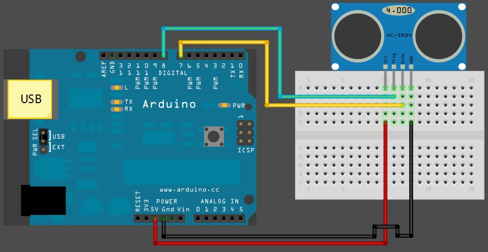
Connected Vcc with 5v. Ground to 0v. Trigpin and echopin are connected to pins 8 and 7 respectively of arduino.
Code is given below. So, after the code is uploaded to arduino, press Ctrl + Shift + M to start the Serial Monitor. You can see the distance in cm as well as inches that we are printing after converting the signal recieved from the sensor.
Code:
const int trigPin = 8;
const int echoPin = 7;

void setup() {
	Serial.begin(9600);
}

void loop()
{
	long duration, inches, cm;
	pinMode(trigPin, OUTPUT);
	digitalWrite(trigPin, LOW);		//sending

	delayMicroseconds(2);			//a

	digitalWrite(trigPin, HIGH);		//10uS

	delayMicroseconds(10);			//electronic

	digitalWrite(trigPin, LOW);		//pulse

	pinMode(echoPin, INPUT);
	duration = pulseIn(echoPin, HIGH);	//measure time taken by echo pin to go from low to high

	inches = Inches(duration);
	cm = Centimeters(duration);
	Serial.print(inches);
	Serial.print("in, ");
	Serial.print(cm);
  	Serial.print("cm");
  	Serial.println();
  	delay(100);
}

long Inches(long microseconds)			//convert time to inches

{
	return microseconds / 74 / 2;

}

long Centimeters(long microseconds)		//convert time to cm

{
	return microseconds / 29 / 2;
}