The Raspberry Pi (read R-pi) is a series of low-cost, credit card-sized single-board computers. It is just like any other computer and features built in Wi-Fi, Bluetooth. You can connect a keyboard, mouse through USB or Bluetooth and a display monitor through HDMI cable and start using it just like a normal computer.
But the real power of Rpi is realized in embedded systems. The Raspberry Pi has the ability to interact with the outside world, and has been used in a wide array of digital maker projects, from music machines and parent detectors to weather stations and tweeting birdhouses with infra-red cameras.
Contents:
First Look
What does Raspberry Pi board look like?
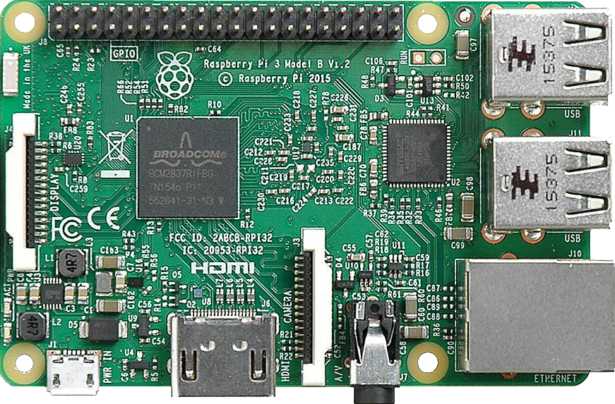
The image given below is a top-view of Raspberry Pi 3 model B.
-
The 40 pins shown at the top contain the Ground pins, I2C, SPI, GPIO pins, supply voltage pins.
-
On the right, the top two structures are the USB ports and bottom one is the ethernet port.
-
Comming down, we have the USB charging port on the left and the and the HDMI port next to it.
-
On the left hand side we have a micro SD slot which acts as the hard drive of Raspberry Pi.
Now lets have a closer look at those 40 pins. Here is a pin diagram of those 40 pins.
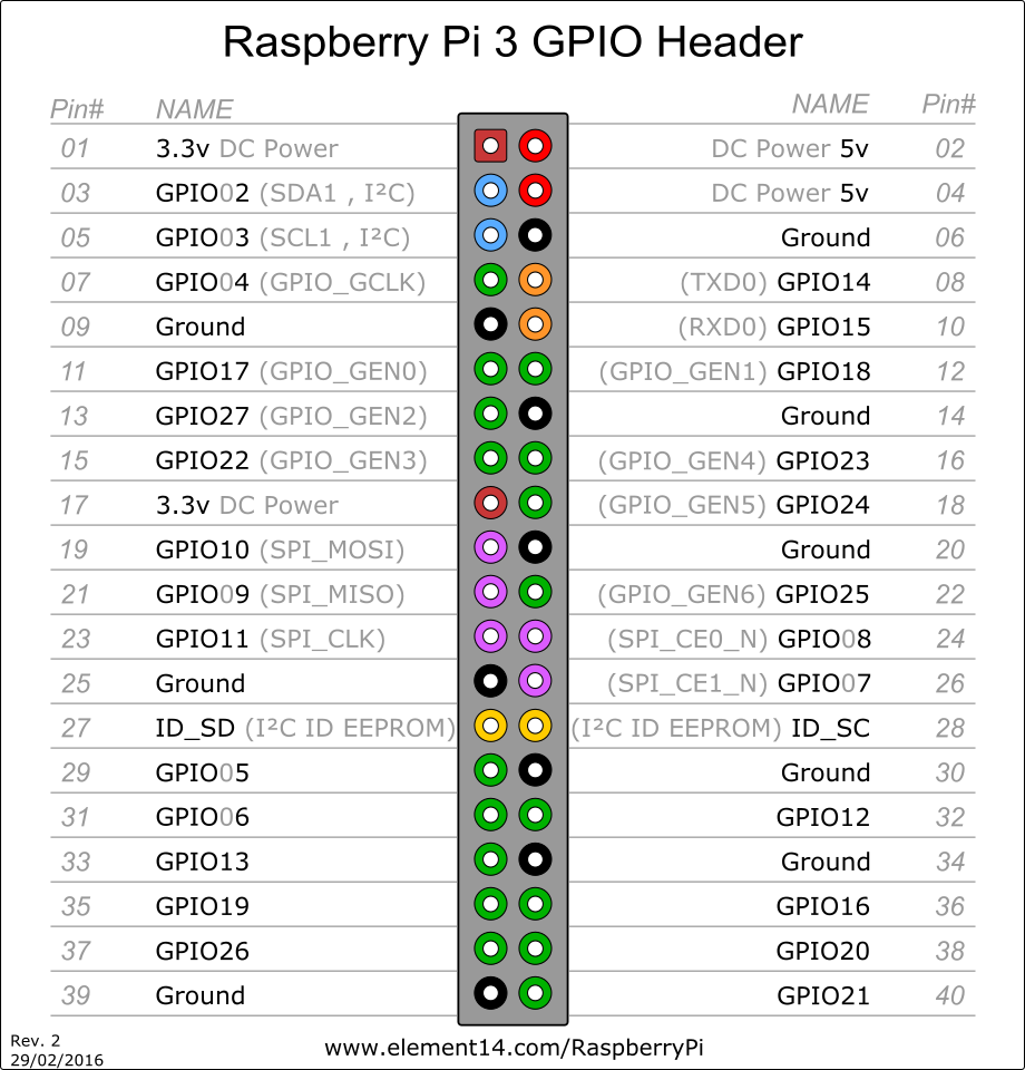 We can see that out of the 40 pins
- 27 pins are GPIO pins
- 8 pins are Ground
- 2 pins are 5V supply
- 2 pins are 3.3V supply
- The other 2 pins are ID_SD and ID_SC used in I2C communication
The GPIO pins are used to connect to electronic devices and can be used as input or output. GPIO 2 and 3 can be used for I2C communication as they are the SDA and SCL pins respectively.
The 5V pins can be used to give 5V supply to any of the electronic devices. Same goes for 3.3V pins.
Installation
Depending on whether your laptop/pc has Linux or Windows, follow this steps to set your Raspberry Pi.
For Linux
- First download the image file of the operating system you want to install on your R-pi.
- Open a linux terminal of your choice.
- Connect your R-pi to laptop using the connector and insert the memory card in its slot.
-
Now unmount the memory card using command:
sudo umount /dev/PORT_NAMETo see which port your sdcard belongs to, type:
lsblk -
To copy the contents of img file to sdcard, type:
sudo dd if=PATH_TO_IMG_FILE of=PATH_TO_SD_CARD_MOUNT_POINT - It may take some time to copy the contents. Once done, you are ready to configure your r-pi.
For Windows
- First download the image file of the operating system you want to install on your R-pi.
- Download Win32DiskImager and unzip the application (.exe file) inside.
- Insert your SD card into your Windows PC using a card reader.
- Open Win32DiskImager.exe with Administrator privileges ( That is, right click on it and choose “Run as Administrator” ).
- If your SD card isn’t automatically detected by the application, click on the drop-down menu at the top right (labeled “De
- Click the Write button and wait for Win32DiskImager to do its thing. When it finishes, you can safely eject your SD card and insert it into your Raspberry Pi.
For OSX
- First download the image file of the operating system you want to install on your R-pi.
- Download RPi-sd card builder (be sure to pick the appropriate version for your installed version of OS X) and unzip the application.
- Insert your SD card into your Mac using a card reader.
- Open RPi-sd card builder. You’ll immediately be asked to choose a Raspbian image. Choose the .img file you downloaded earlier.
- You’ll be asked if your SD card is connected. Since we inserted it earlier, it is, so go ahead and click Continue. You’ll be presented with SD card options. If you only have one inserted, you won’t see anything else in the list and it’ll be checked. If not, just check only the card you want to use and click OK.
- Enter your administrator password and click OK. You’ll be asked if the SD card was ejected. This is supposed to happen, as the application needs to unmount it so it can perform a direct copy. Double-check that your SD card is no longer available in the Finder. DO NOT remove it from your USB port. When you’re sure, click Continue.
- RPi-sd card builder finishes prepping your SD card, safely eject it and insert it into your Raspberry Pi unit.
Time to configure your R-pi!
Configuration
We use SSH to control R-pi through our laptop for SSH, we need r-pi to be connected to some network.
We can configure R-pi’s SSH, without ever requiring to boot R-pi.
Once the OS image has been burned on the SD-Card, remount the SD-card. You will see a lot of folders required by the OS to boot. We will change some configuration files before we insert the SD-card into R-Pi so that our R-Pi can directly connect to WiFi networks and you can SSH into it.
WiFi password setting
Open /etc/wpa_supplicant/wpa_supplicant.conf in the SD-card
and write following piece of code in it at the end:
network={
    ssid="WIFI_NAME"
    psk="WIFI_PASSWORD"
    key_mgmt=WPA-PSK
}
Enable SSH
Edit file /etc/rc.local and add the following line at the end
/etc/init.d/ssh startNow remove the SD-card, put it in the R-Pi and power it up. You should see a red power light and a green light flashing up, if the OS boots correctly.
After some time, connect to the R-Pi using SSH. On linux, you can run the
command ssh pi@raspberrypi.local, or use PuTTY on Windows/OSX.
Note: raspberrypi.local is an identifier for R-Pi’s connected to your local network,
hence you don’t need to specify the exact IP address. Though, if you know the IP
address, you can specify that too instead.
Enter the default password raspberry, and the RPi terminal will be accessible
looking something like this
udiboy:~$ ssh pi@raspberrypi.local
pi@raspberrypi.local's password:

The programs included with the Debian GNU/Linux system are free software;
the exact distribution terms for each program are described in the
individual files in /usr/share/doc/*/copyright.

Debian GNU/Linux comes with ABSOLUTELY NO WARRANTY, to the extent
permitted by applicable law.
Last login: Mon May  1 13:19:06 2017 from 192.168.0.120
pi@raspberrypi:~ $
Change the password of the RPi by running passwd.
And that’s it! You are done setting up!
Static IP configuration
Note: Static IP configuration is no longer required because recent versions of the RPi OS have a discovery protocol enabled which lets you SSH into the RPi without knowing the IP address.
This can be done by editing the file on your PC too.
We will assign a static IP to the R-Pi so that every time it connects to WiFi, it uses the same IP, hence we know what IP the R-Pi has.
You will need to know the IP address format, netmask and gateway of your network. For Tinkerers’ Lab, it is
IP = 192.168.0.*
Netmask = 255.255.255.0
Gateway = 192.168.0.1
For setting static ip, open /etc/network/interfaces.d (again by mounting the
SD-card)
You will see a line reading iface wlan0 inet manual
Change manual to static
and add the following lines
    address 192.168.0.42
    netask 255.255.255.0
    gateway 192.168.0.1
Once configured, type ssh pi@<ip-address> in terminal to connect to your R-pi.
GPIO Pins
Configuring GPIO
For programming the GPIO pins we have to install the python 2 library RPi.GPIO. This module makes it simple to use the GPIO pins. To install RPi.GPIO on your Raspberry Pi follow the following instructions.
In the LXTerminal of your R-Pi type the commands
sudo apt-get update
To install RPi.GPIO, you first need to install the Python Development toolkit that RPi.GPIO requires.
To do this enter the following command:
sudo apt-get install python-dev
Then to install Rpi.GPIO itself type:
sudo apt-get install python-rpi.gpio
Thats it! Now you are ready to program GPIO pins.
Basics of GPIO programming
To program GPIO pins you have to import RPi.GPIO library in your python program. To do this type the following line at the top of your program:
import RPi.GPIO as GPIO
But before we start programming we have to set the numbering system of the pins. There are two types of numbering systems:
- BOARD
- BCM
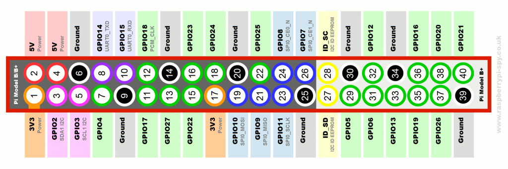
The GPIO.BOARD option specifies that you are referring to the pins by the number of the pin the the plug - i.e the numbers printed on the board (e.g. P1) and in the middle of the diagrams below.
The GPIO.BCM option means that you are referring to the pins by the “Broadcom SOC channel” number, these are the numbers after “GPIO” in the green rectangles around the outside of the below diagrams:
In the image below the numbers in the middle correspond to BOARD numbering and those written outside refer to BCM numbering.
Based on which numbering system is comfortable to you, which RPi shield your are using, what program you are using you can choose the numbering sytem which is most convinient to you.
To specify in your code which number-system is being used, use the GPIO.setmode() function. For example…
GPIO.setmode(GPIO.BCM)
or
GPIO.setmode(GPIO.BOARD)
After specifying the numbering system we have to decide whether the pins that we are using will be input or output (just like in Arduino).
To do this we use GPIO.setup() function. So if you want to setup pin 4 as output you would enter:
GPIO.setup(4, GPIO.OUT)
If you want to set pin 17 as input you would enter:
GPIO.setup(17, GPIO.IN)
So if you have set a particular pin as input you would like to read the value of that pin. To do this you would use the GPIO.input() function.
For example if you would like to read the value of pin 17 you would enter:
GPIO.input(17)
If you have setup a pin as output you would like to write a value to it. You would use the function GPIO.output() for it.
For example if you would like to set the value of pin 4 as HIGH you would enter:
GPIO.output(4, GPIO.HIGH)
If you want to set it as low:
GPIO.output(4, GPIO.LOW)
Now that you know how to set input and output of pins you are set to use any electronic devices along with the entire convinience of python.
One important thing to note that after the program is terminated either on its own or by a Keyboard Interrupt some of the pins which were high remain high after execution of the program. So in order to set everything to low we use the GPIO.cleanup() function.
Here is an example of simple LED blink program in which the usage of each and every function will become clear
    import RPi.GPIO as GPIO
    import time
    GPIO.setmode(GPIO.BCM)
    GPIO.setup(4, GPIO.OUT)

    try:
	    while True:
	    	GPIO.output(4, GPIO.HIGH)
	    	time.sleep(1)
	    	GPIO.output(4, GPIO.LOW)
	    	time.sleep(1)
	except KeyboardInterrupt:
		GPIO.cleanup()
When we execute this program with a led at pin 4 we would see the LED blinking at a rate of 1 second. This program would go on for ever unless we terminate it by CTRL-C which is a KeyBoardInterrupt which then initiates the GPIO.cleanup function.
With this much knowledge you should be able to interface any electronic equipment with R-Pi with one last precation :P.
All the GPIO pins on R-pi are 3.3 volt logic level. So it is not safe to connect any device that gives or takes more than 3.3v as it might damage the GPIO pins. If you have to use any device that has a 5V supply such as HCSR04 ultrasonic sensors you should use a potential divider.
Time to try some good projects with your R-pi. Happy tinkering!