In the First semester along with Pranav, I tried to design a burglar alarm circuit that would go off if the burglar tripped over a copper wire. We built a small scale working model of the circuit and presented it in one of the How Things Work Session which is organised by the Robotics Club in association with the Electronics Club of IIT Bombay.
This how we went about designing and building the circuit.
Introduction
A burglar alarm is basically an intruder alert system used to prevent theft/robbery and protect one’s premises. The circuit that we have built over here can be easily built and understood by anyone who has enthu!! Most of the components will be available at Tinkerer’s Lab so take a good look before buying anything.
So, Let’s dive in
Concepts and Basic Principles
Well, the basic idea is that when someone trips over the copper wire and it snaps the circuit is broken which then triggers an impulse and the speaker starts buzzing.
How is the impulse triggered?
Here we make use of 555 timer IC.
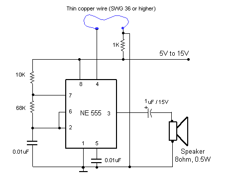
The figure shown below shows us the basic circuit.

The main pin which is of interest to us is PIN 2 - It turns on the output when the voltage supplied to it drops below 1/3 of Vcc.
So one can imagine one end of the copper wire being connected to PIN 2 and one end of the speaker being connected to PIN 3. The other end of both these entities would obviously be connected to the ground. When the circuit breaks the voltage at PIN 2 drops below the threshold which triggers an output at PIN 3 due to which the speaker starts buzzing.
The only question now remaining is how does the 555 Timer work?
In this project we operate the 555 timer in Monostable mode.
And what is Monostable mode?
This mode works on the principles of Monostable multivibrator. A monostable multivibrator is an electronic circuit that generates an output pulse. When triggered, a pulse of pre-defined duration is produced. The circuit then returns to its quiescent state and produces no more output until triggered again.
And this is exactly what we need!!
So now having our concepts on solid foundations we can move on to actually building the circuit!
Components Required
- 555 Timer IC
- Speaker
- Copper wire pf appropriate resistance
- Resistance and Capacitors
Burglar Alarm Circuit Diagram

Build the Circuit
What you need to do is produce the exact replica of the above schematic diagram on your breadboard. In theory this sounds simple but we faced a number of problems and we hope to document all of them down in high hopes that you don’t run into them.
After making it try detaching one connection of the copper wire. If you’re speaker buzzes Yayy!!! You’ve done it!. Although the circuit was simple the underlying concepts lay the foundations for a number of complicated projects.
Problems faced by us
- Use the exact values of capacitors and resistances or any other values based on precise calculations as the working of the circuit is greatly dependent on these variables
- Even the type of copper wire has been specifically chosen and we did run into lot of debugging problems due to this. Just make sure NOT to use the thin copper wire that is available in wires.
Extend this project
The concepts we laid down here are the foundations of any burglar alarm systems in general. Burglar alarms or alert systems can be designed in different ways; from very simple sound alarm system (the one we made) to the advanced and feature rich system which will send SMS alerts, activate sound alarm, turn ON lights, turn ON CCTV cameras, close the main gate etc. We hope you can take on the more advanced ones!
Hope you had a great time reading this and were able to learn something new!!