Last year I entered IIT Bombay and had my first face off with the modern tech then. We had a bot racing competition called XLR8 in which we have to prepare a bot on our own and race it with others so as to win. Seems easy? Not as much as it seems to be .
It’s not just about making and winning, it’s about learning too . All the components we are getting and assembling we should have knowledge about them. How, when ,where they work and are used should be thing we should really be taking care of . So while we were making the bot we came across this most intriguing small chip, L293D. This is basically a motor driver, something which helps in controlling motors (in our case, the wheels of the bot). A first look at the connections and we feel it’s all too mixed up! Wires entangled into one another and what goes where, NO IDEA!
But actually it’s working is pretty easy. Here, I will try to explain it in a simple way.
So let’s explore this motor driver and see what we can do to learn it (at least with a data sheet :P )
Presuming we have this driver , its datasheet and zeal to learn.
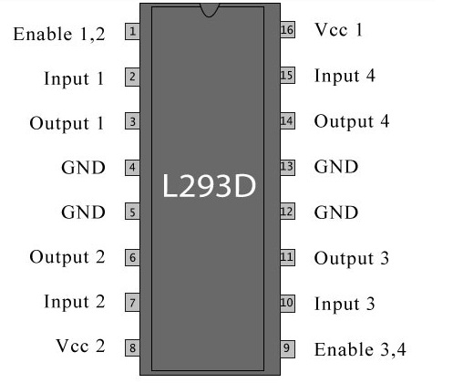
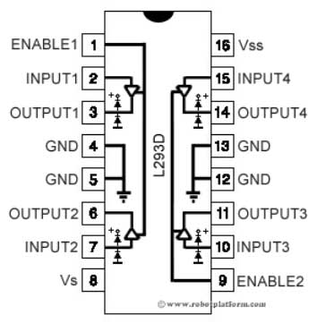
It looks like this from outside and the connections inside are :
Working Of L293D
L293D is a motor driver 16 pin IC which can be used to run a set of two DC motors at a time. To power itself it requires 5V voltage through VCC1 and can deliver up to 12 volts through VCC2.
To understand the working of L293D, we first need to know about a component called H-Bridge
H-Bridge
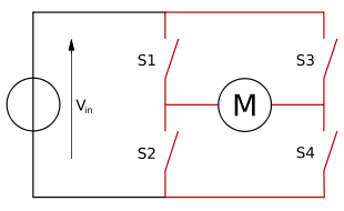
A H-bridge looks like following :
It is used to apply voltage across a load( here, a motor ) in both the directions. So we can easily infer from this if the voltage across the motor is reversed , its direction of rotation is also reversed and hence this is used to drive the motor in both the directions.
- If switches S1 and S4 are closed then motor rotates clockwise.
- If switches S2 and S3 are closed then motor rotates anticlockwise.
- If S1 and S3 or S2 and S4 are closed then motor stops rotating.
- If all are left open motor moves freely.
- Never close S1 and S2 or S3 and S4 or all of them simultaneously.
L293D is, infact, a dual H bridge IC used to drive motors in both forward and backward direction through various combinations of inputs that we will look later. The first H-Bridge is formed by Left Hand Side pins of L293D (see diagram) while the second is formed by the right hand side ones.
To ensure that motor attach to it at both sides run, PIN 1 and PIN 9 ( ENABLE PINS ) should be high. Enable pins can be a considered as a switch to this IC , if it’s high then switch is on and motor will work ( according to the provided proper input ) and if it is low, meaning switch is off, the motors won’t respond to the corresponding inputs.
The voltage we supply at VCC1 is used to power the L293D for its working and at VCC2 we get the output used for driving its motors. Now the output at VCC2 depends on the voltage you supplied at VCC1. The fraction of voltage you supply at VCC1 appears in the same fraction at VCC2.
CONNECTIONS IN L293D
-
Pin1 and Pin9 are “Enable” pins or the switch pins as you can say. They should be connected to +5V for the drivers to function (for the motor to follow the inputs). If they pulled low (GND), then the outputs will be turned off regardless of the input states, stopping the motors.
-
Pin4, Pin5, Pin12 and Pin 13 are ground pins which should ideally be connected to microcontroller’s ground.
-
Pin2, Pin7, Pin10 and Pin15 are logic input pins. These are control pins which should be connected to microcontroller pins or whatever is the input to L293D. Pin2 and Pin7 control the left motor ; Pin10 and Pin15 control the right motor. (as shown in diagram)
-
Pin3, Pin6, Pin11, and Pin 14 are output pins. Tie Pin3 and Pin6 to the left motor, Pin11 and Pin 14 to right motor. Note that there is a bijection between the input pins and output pins.
-
Pin16 powers the IC and it should be connected to regulated +5Volts.
-
Pin8 powers the two motors and should be connected to positive lead of a secondary battery. As per the datasheet, supply voltage can be as high as 36 Volts.
As we can see the highest output is 36V so considerably larger motor can also be driven using this IC. ( Oh I see this IC is useful :P )
Keep in mind all these connections while making your bot as well the reason behind these connections. This makes debugging easy. I have experienced this, we randomly did all the connections and wondering why our bot isn’t working until some told enable pin is set too low!
LOGIC TABLE FOR L293D

Similarly for PIN 9 ( ~PIN 1 ) , PIN 10( ~PIN2 ) and PIN 15 ( ~PIN7 ).
EXPLANATION OF THE TABLE
Now no need to memorize the high and low , work on the logic !
PIN 1 and PIN 9 are your enable pins so they need to be kept high and
otherwise it doesn’t matter what your input is , your motors will not
move.
Now we should have a potential difference between the output terminals,
so that it appears across motor and it rotates. For that to happen there
should be a potential difference at the input terminals too (since there
is a bijection between the input and output pins) ! Hence, the truth
table is justified.
DO’s AND DONT’s
You have learnt about L293D but before moving on to any kind of tinkering you should know what to experiment and what not to ( unless you are so enthusiastic to see whats like a blown up L293D). Here we go:
-
Make sure you connect all the pins properly such that no two pins are shorted except the ground pins.
-
Make sure the IC is connected in proper orientation. The pin to the left of the small semicircle of the IC at the top is the first pin.
-
Make sure the supply voltage is not greater than 5 volts for IC and more than 36 volts for motor.
-
Remove the input pins when not required to avoid any unnecessary heating of IC.
Happy tinkering ! :D