Greetings from Electronics Club IIT Bombay
We conduct Electrified sessions regularly wherein some basic electronics concepts are discussed and some cool DIY projects based on the concepts discussed are made.
On 23rd september, 2016 we conducted Electrified 2 where we discussed Operational amplifiers, transistors, sensors, and some awesome circuits using these devices.
An overview of the content we covered.
Operational Amplifiers
Op-amp, as often called, is an extremely versatile devices which is fundamentally a voltage amplifying device. Using opamps we can amplify, filter and do a lot more with signals. Also in addition to that we can perform mathematical operations such as addition, subtraction , integration and differentiation etc.
For more details of Opamps you can refer our tutorial on basic electronics.
Bipolar Junction Transistors
Transistors are three terminal active devices made from different semiconductor materials that can act as either an insulator or a conductor by the application of a small signal voltage. The transistor’s ability to change between these two states enables it to have two basic functions: “switching” (digital electronics) or “amplification” (analog electronics).
Enough of boring theory I guess, let’s get started with the circuits.
Projects
Xyloband
Have you ever seen the xylobands which we wear in concerts and they flash light according to the music being played. You can make it on your own with just basic knowledge of opamps !
Formally the problem statement would be make an LED blink on the beats of music.
Now the beats of music are essentially the drum sounds which are of the lowest frequency. So essentially we need to isolate the sound signals produced made by a drum, amplify them and then make LED toggle on that frequency.
Here is the circuit of xyloband:
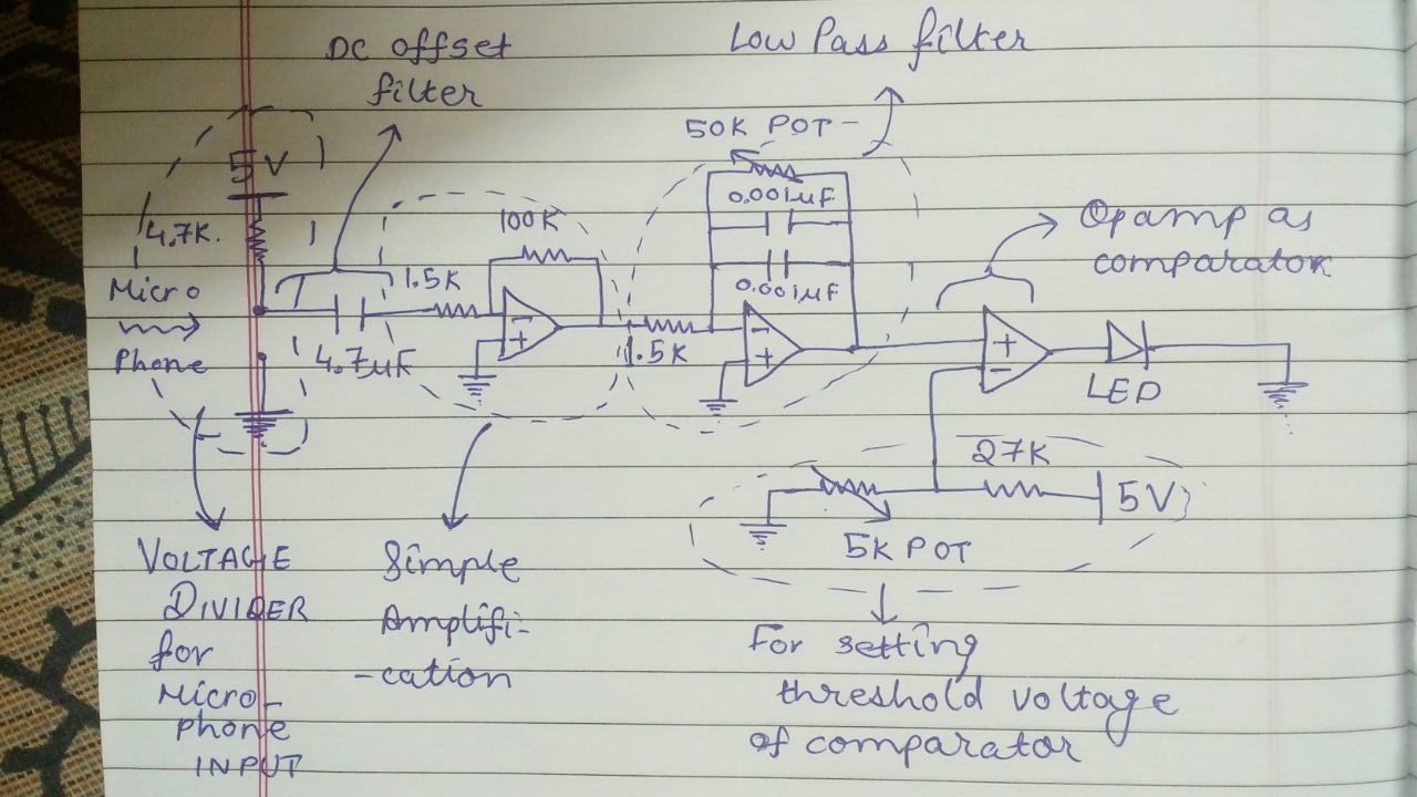
We start by taking the input of music via a microphone. We can model the microphone as unipolar resistor. Therefore we have made a voltage divider circuit in which one resistor is the microphone itself. When the sound waves hit the microphone, the resistance of the microphone changes according to the music.
So theoretically we have a voltage output of music but you can’t directly apply this output to the LED. The reasons being :
- The voltage output is in order of about 10-20 millivolts.
- The output contains all the frequencies.
To amplify the signal we are using opamps.The next part of the circuit you can see is an inverting voltage amplifier made by using an Opamp. The gain factor of this amplifier is simply the ratio of resistances connected which is 100/1.5 = 66.67.
Now we need only the signals corresponding to the drum frequencies. But we have all frequencies corresponding to all the instruments. We need to “filter” out these frequencies. Since the frequency we want is the lowest of all we need to design a low pass filter.
Here too opamp comes to help. As you can see in the circuit we have designed a low pass filter using opamp. The values of resistor and capacitor is chosen such that the cutoff frequency of the filter is just above the maximum frequency of drum beats.
Now after filtering the signal this is what we have in our hands : An amplified output corresponding the the beats of the music. Note that after filtering the higher frequencies have been attenuated.
Now what I want is that if I get the amplified output of drumbeats the my LED should turn ON and if get the attenuated voltage of higher frequencies then my LED should be OFF.
So basically we need to “compare” the signals with respect to a particular value. So that’s what our next part of the circuit is; a comparator. The reference voltage of comparator has been set by using a simple voltage divider.
And we are done with our circuit and you are ready to make the LED dance on your music beats.
Audio Amplifier
In this circuit we play music through our cell phones via an external speaker.
Here is the circuit diagram of the Audio Amplifier:
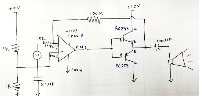
Can you see an AC source in the left part of circuit ? That’s where we connect the audio jack output from our cell phones.
Now to drive a speaker we need sufficient voltage and current. The current and voltage that we receive from the audio jack is not sufficient to drive the speaker. Therefore in the above circuit we are amplifying the signal in two stages; one is voltage amplifier and the another one is current amplifier.
The voltage amplification is done by opamp. The current is amplified using a differential amplifier made by an npn and a pnp transistor. The final output is then connected to the speaker and you have the speaker playing the music.
Let’s have a look at how the things turned out to be :)